Sign up to our newsletter
Click to register!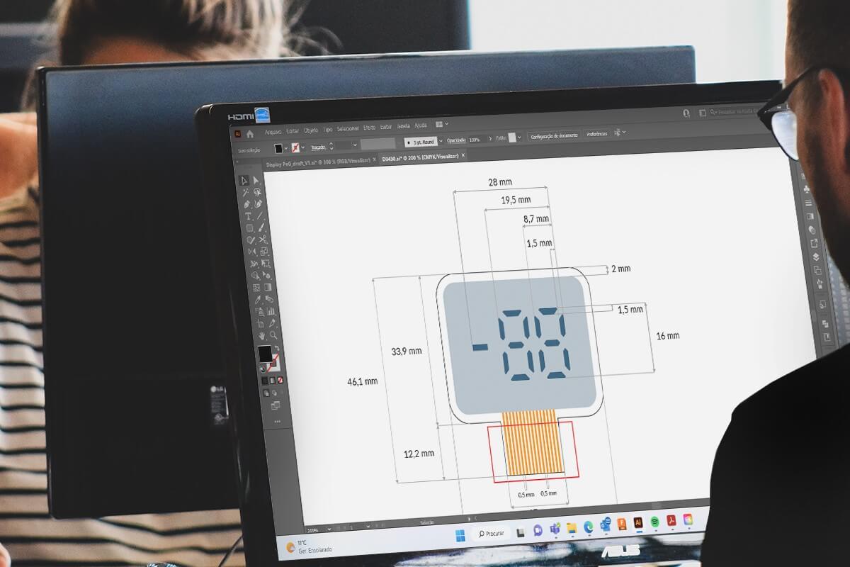


This article will guide you through the design rules that are applicable when designing customized electrochromic displays from Ynvisible. Please do not hesitate to contact sales@ynvisible.com for additional guidance.
Four main design constraints need to be followed to ensure proper performance. First, there must be a transparent border of 2 mm around the edge of the display. Second, a 2 mm distance between the edge of the visible area and the active area is required. Third, the clearance between the individual segments needs to be at least 1,5mm. Finally, there needs to be a 3 mm distance between the active area and the exposed connectors. All distances are summarized in the table below:

We have successfully manufactured devices with up to 80 segments. However, we highly recommend minimizing the number of segments used in your design as much as possible to simplify integration. Typically, we recommend designs with less than 30 segments.
Larger segments require longer pulse lengths to switch. The required pulse lengths range from hundreds of milliseconds in the mm2-regime to seconds in the cm2-regime.
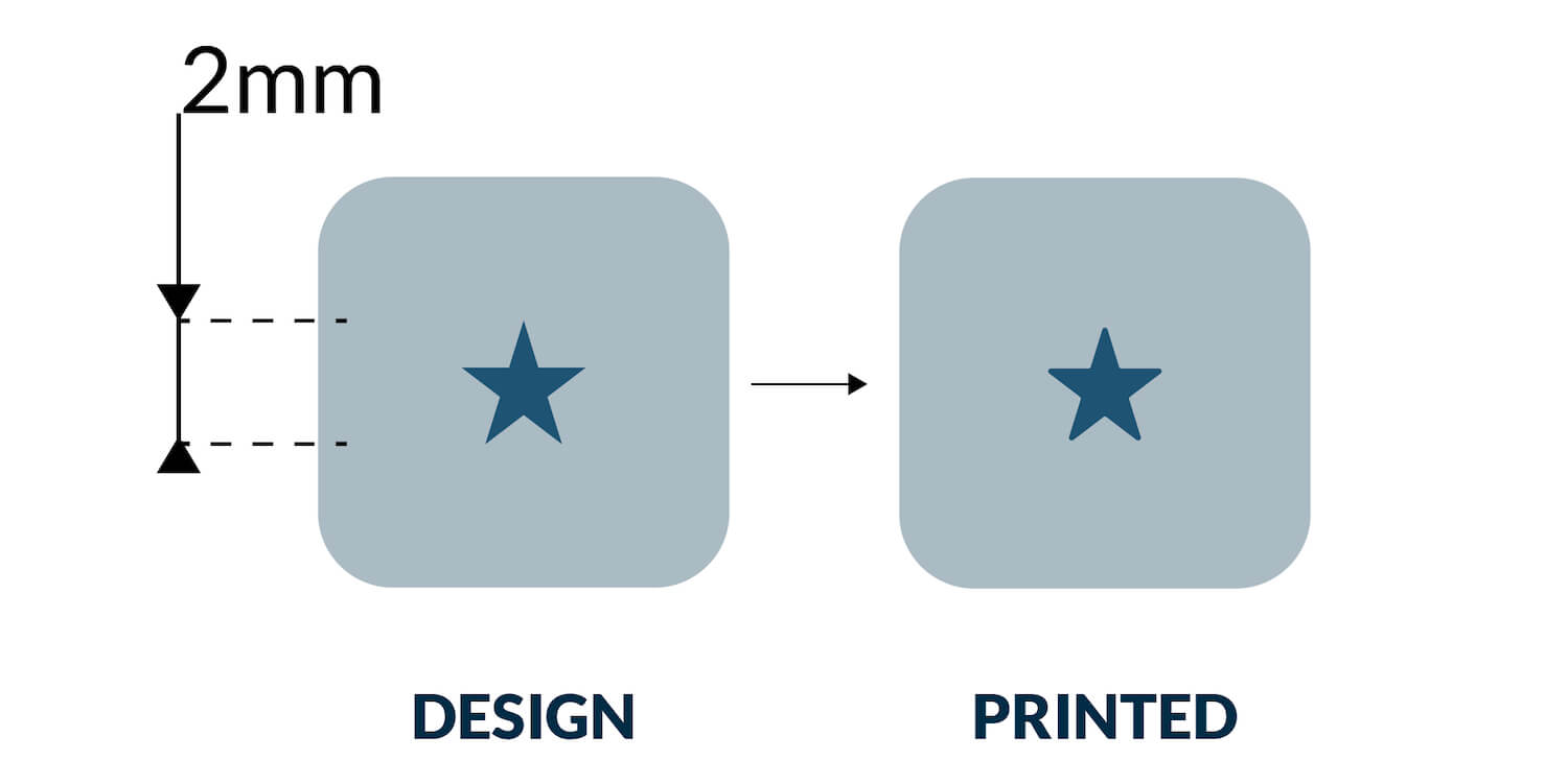
Small angular features will be slightly rounded in production as a result of the screen printing process. The image below shows an approximation of the difference between a computer design and the printed version. We don’t recommend features smaller than 1 mm2.
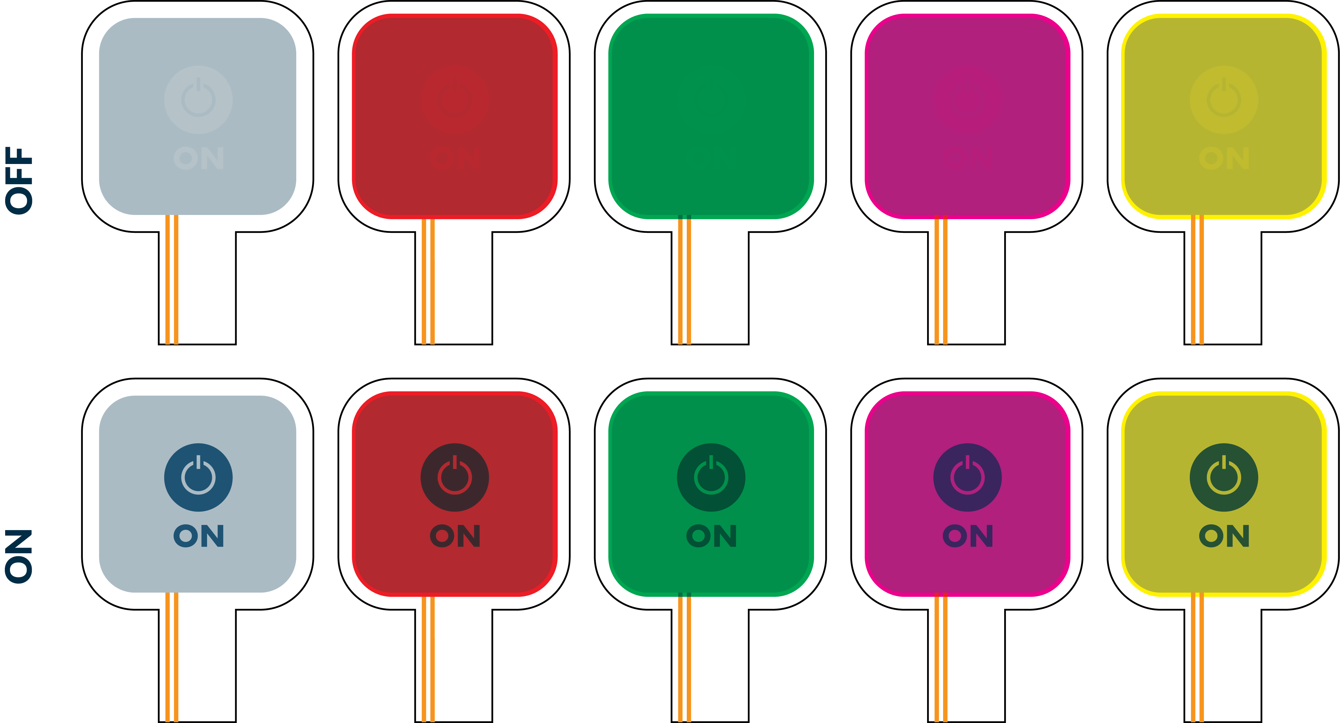
We offer displays in a wide range of colors and can customize tones to match your brand. In our custom prototype manufacturing, we offer a few standard colors; Grey, Red, Green, Magenta and Yellow. The grey color offers the best readability. An approximation of the colors in the “ON” and “OFF” state can be seen below.
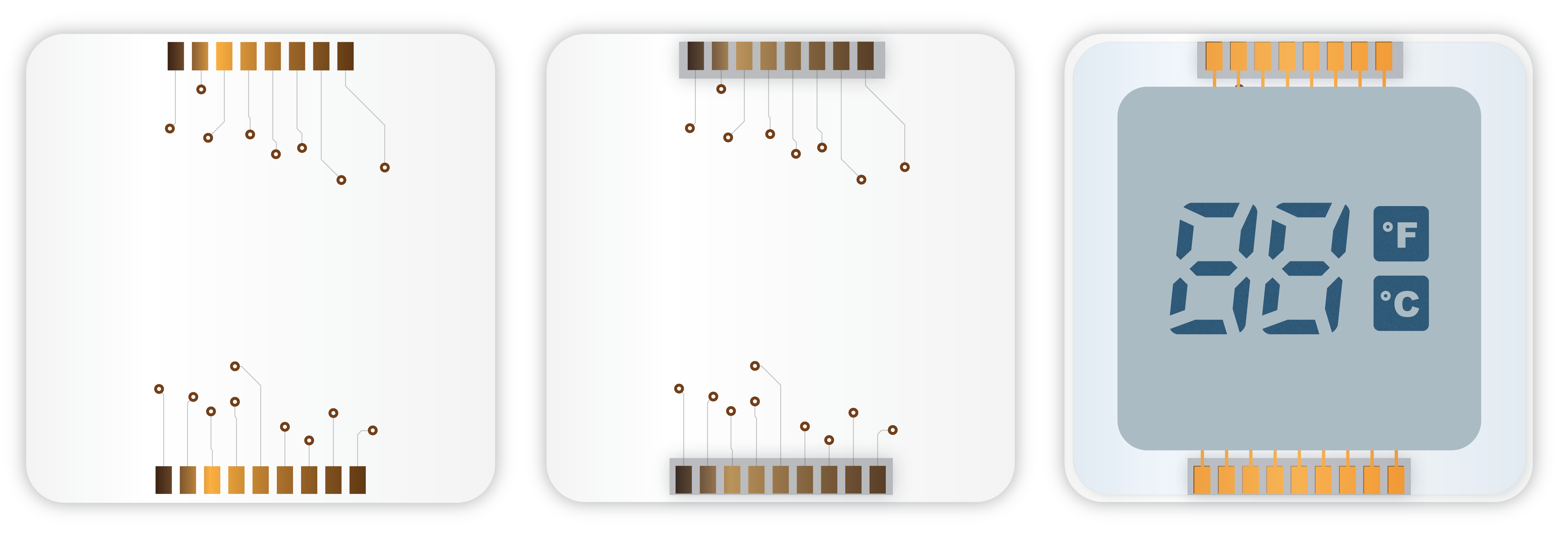
The connector can be designed according to your requirements. The number of electrodes required for a design equals the number of segments plus one additional electrode for the common electrode, i.e.for a 15-segment display, the number of electrodes would be 16. The minimum distance between the electrodes needs to be a least 250 µm.
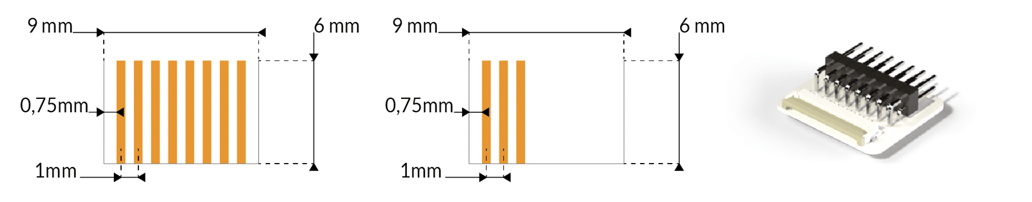
To get started quickly, we recommend our standard connector layout for 1mm pitch connectors. Ynvisible offers 16-pin ZIF to pinhead adapters for evaluation purposes. We suggest using a tail layout optimized for an 8-pin connector if the number of segments is 1-7 and a 16-pin connector if the number of segments is 8-15. If you have more segments, please contact a sales representative for more information.
There are lots of connectors to choose from, two suggestions are:
ACF is a common material to connect a multitude of displays to PCBs (both rigid and flex) thanks to its ability to connect many pins at a low cost. ACF films are only conductive in the z-direction (vertical), which means that one single piece of film can connect all the display pads without any short circuits. The ACF contains small, separated particles that connect in the z-direction when heat and pressure are applied with a hot bar. Recommended products:
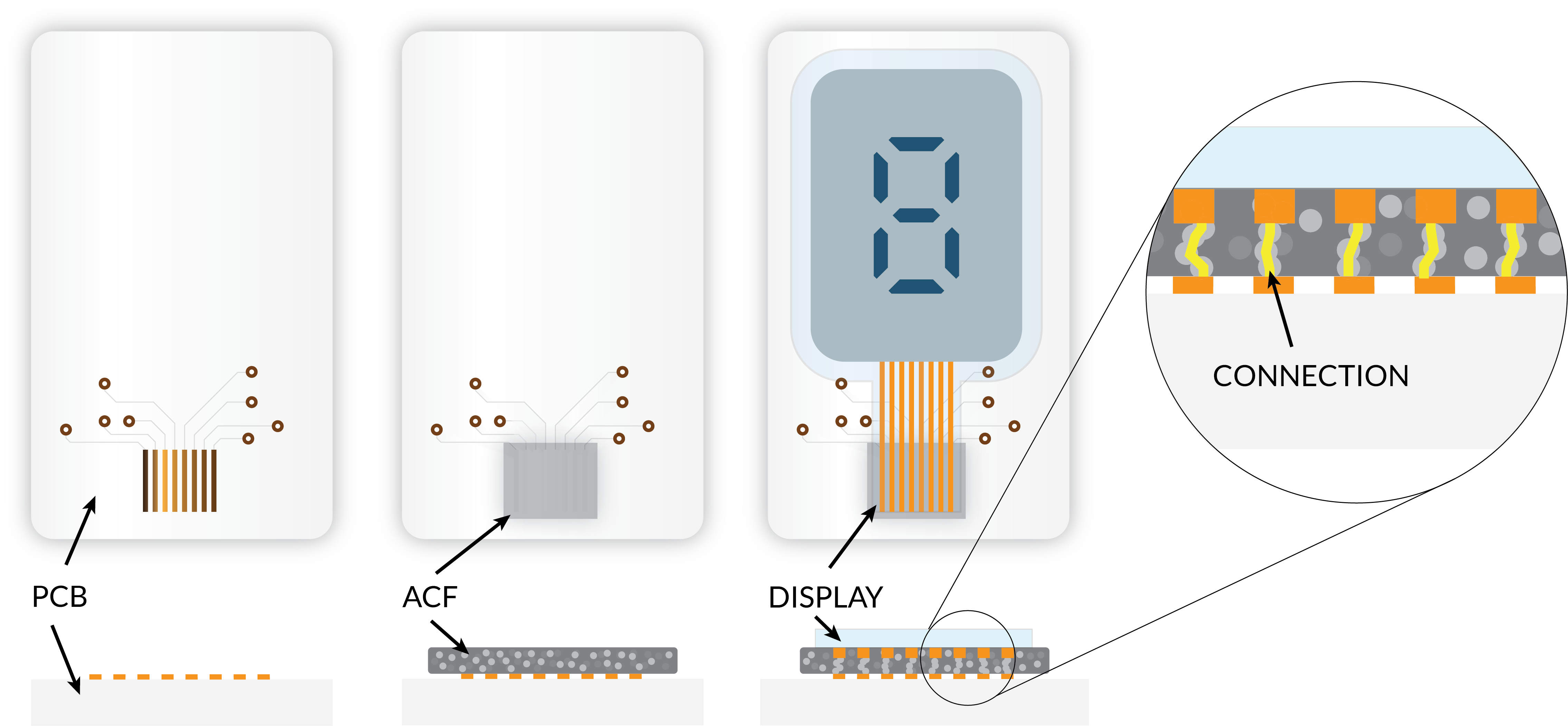
For a typical ACF, the process looks as follows:
By using ACF, the connector pads can be spread out on one or multiple of the edges. Placing the components on the opposite side of the display creates a completely flat front and, at the same time, a strong mechanical connection; see the image below:
Please read our article about prototype production to learn more about the overall process.
One way to get started is to use the template below including the same display designs as we use in the Segment Display Kit. The PDF is Adobe Illustrator compatible, which is Ynvisible's preferred software for designing displays. However, any vector based format will work fine.
Press releases, success stories, and educational content from Ynvisible University.
Learn more 

.png)