Sign up to our newsletter
Click to register!We always try to make it easy to learn more about our displays and their benefits. Please watch the video below for step-by-step instructions, and do not hesitate to contact support@ynvisible.com if there are any questions.
Detailed Driver Instructions Open Display DatasheetWe’re really happy that you’re interested in our ultra-low-power, thin, and flexible displays. The kits have been developed for testing and rapid prototyping purposes. This guide contains all instructions needed to get started and to learn more about our Segment Displays.
The standard Segment Display Kit contains the following items:
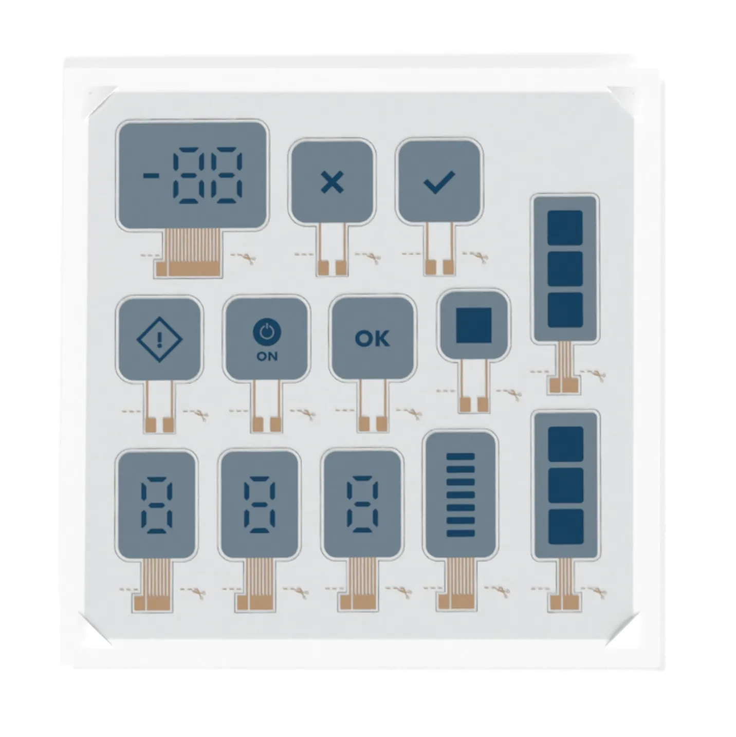
1. Ynvisible Segment Displays
Electrochromic segment displays with different segments, shapes, and symbols, suitable for testing and evaluation.
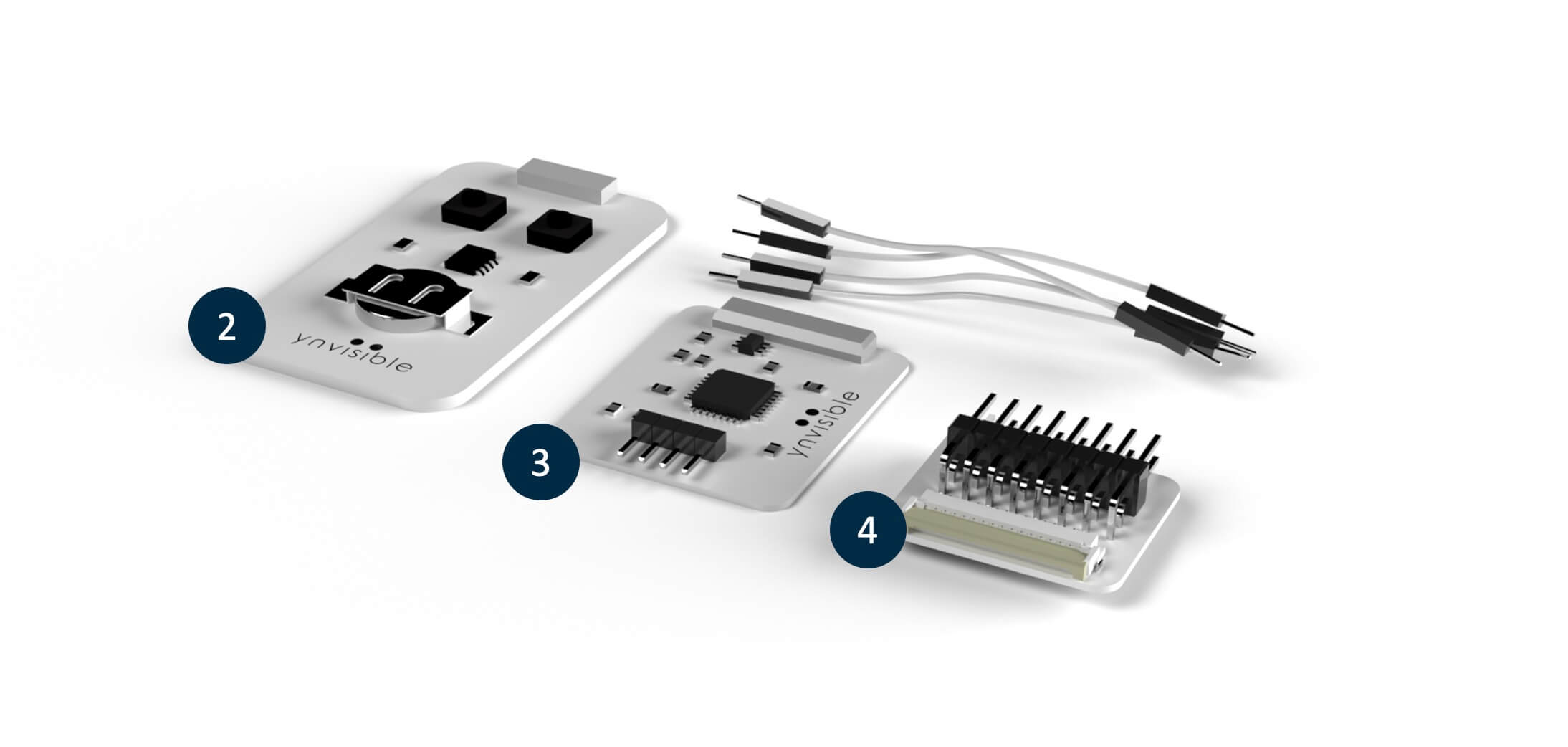
2. Manual Display Clicker
Manual display controller for ON/OFF operations
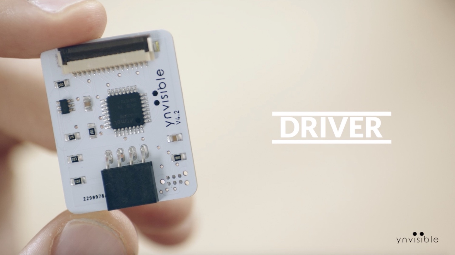
3. Display Driver and Software Library
Dedicated display driver with I2C communication interface. Compatible with Arduino and other easy-to-use development boards.
4 Flexible Display Adapter
For convenient connection of the flexible displays on a plastic substrate to rigid electronics (such as development boards), using a FFC/FPC connector.
We recommend to start with the Clicker to get a feeling for how the displays behave when a positive, negative, or no voltage is applied. You can also activate the display and disconnect it from the Clicker to observe the image memory effect.
An optional starting point is to read about the fundamentals of electrochromic displays to understand what an electrochromic display is and how it works.
No matter your level of expertise you will be able to use this device.
.jpg)
Step 1: Remove the insulating strip from the battery
Note: please remove the battery if you are not using the device for a long time.
Step 2: Insert the display in the ZIF Connector
Step 3: Drive the display
Caution: Stop applying a voltage when no more color change can be observed. Excessive activation or deactivation may cause damage to the displays.
The display driver is simple and intuitive tool to operate the display. By connecting it to a development board such as an Arduino you can implement it directly into your prototype. With our software library you will be up and running in no time.

Please don't hesitate to contact sales@ynvisible.com if there are questions or comments.
The adapter enables you to delve deeper into the possibilities of driving the display and connect it to your existing system with little or no additional components. Our display can be connected directly to most microcontrollers.
.jpg)
Explore driving protocols and other important information in the datasheet.
There are multiple ways to implement the software and hardware solution for the display driver. Several factors determine the optimal display driving solution:
There are several suggestions regarding both software implementation and driver circuit implementations described in the datasheet. Do not hesitate to contact support@ynvisible.com for additional help.